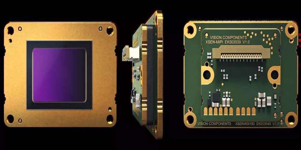
The rapid evolution of the mobile industry has spurred the creation of standards that free system-on-chip designers to concentrate on what makes their solutions unique rather than mundane infrastructure details.
Most notably, the MIPI camera module standardization effort simplifies the incorporation of key smartphone components, including screens and cameras.
Other industries have taken notice of MIPI’s widespread adoption and potency, particularly those working to incorporate new technologies like cameras and screens.
Some Benefits of MIPI CSI-2, DSI, and I3C
High-bandwidth communication between cameras and host processors is made possible by the MIPI CSI-2 standard. The MIPI standards define the interface’s differential physical layer (D-PHY) and employ a dedicated clock to facilitate data transmission.
Camera Control Interface (CCI) is another MIPI standard that defines how to read and write to the camera’s internal registers.
Let’s look at a simplified example to understand how CSI-2 transmits data from a sensor to its host system. To create a packet, a packet builder will grab a line from the frame buffer and use it as a starting point.
Screen Serial Interface for MIPI
By taking in parallel data from the host and serializing it, DSI acts as a fast serial interface between the peripheral and the CPU. The procedure is reversed at the receiving end to reconstruct the parallel information.
The DSI host will bundle the pixel and control data and transmit it to the display in a packet format. DSI may be used in two primary modes: command mode and video mode.
In command mode, the display is assumed to have a local frame buffer to which the host can write. The host can access the register and frame buffer RAM in command mode using DCS commands or vendor-defined commands.
MIPI I3C—Faster, Scalable Sensor Connection
Most modern smartphones include between 10 and 15 sensors, and their connections need up to 18 pins. Typically, a combination of I2C and SPI is used for their connections, with I2C used for the lower data-rate sensors and SPI used for the higher data-rate sensors.
Interrupts, chip selections, and enables are just a few examples of the many sideband signals needed for this method. Due to the lack of a unified driver, the package size and associated complexity and, thus, the associated expenses are increased.
MIPI I3C addresses these problems. It improves upon the two-wire simplicity of I2C while retaining SPI’s high-speed and low-power characteristics by including in-band interrupt, built-in command support, dynamic addressing and maintaining compatibility with I2C sensors.
The I3C Transfer Protocol
I3C data flow can take many forms but always occurs in a frame marked by a Start/Repeated Start and Stop. There will be no changes to how previous I2C transfers are handled. Broadcast messages can be sent to all enslaved people or directed to a specific one using a dynamic address in an SDR system.
For I3C devices to be prepared for HDR transmissions, a broadcast message announcing the transition from SDR to HDR mode is sent before any HDR messages are sent.
MIPI D-PHY
As a low-cost, low-power option, MIPI D-PHY is utilized in hundreds of implementations. Although it has a low-speed, its primary use is for unidirectional, high-speed transmission.
One clock line and numerous data lanes make up the D-forwarding PHY’s DDR clock connection design. Through calibration, static or dynamic de-skew is provided, as is spread-spectrum clocking for resolving electromagnetic interface electromagnetic compatibility concerns.


